Our ESP32 kit

An overview of our purchased ESP32 kit: 95 pieces across 21 items and a plan for simple introductory exercises.

COMPONENT GUIDE

Get to know your kit

Explore how each component works and what you can build with it. All LED types share one article, as do the three types of jumper wires.

16articles
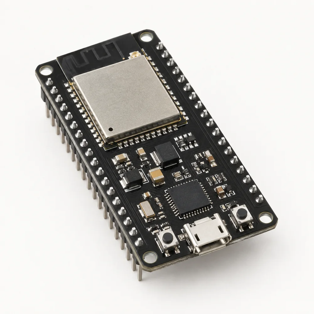
01ESP32 development board with a shielded module, USB connector and two rows of pins.
In the kit: 1 pcs

ESP32 development board

The programmable centre of the kit: reads sensors, controls outputs and connects a prototype to a network.

Explore component
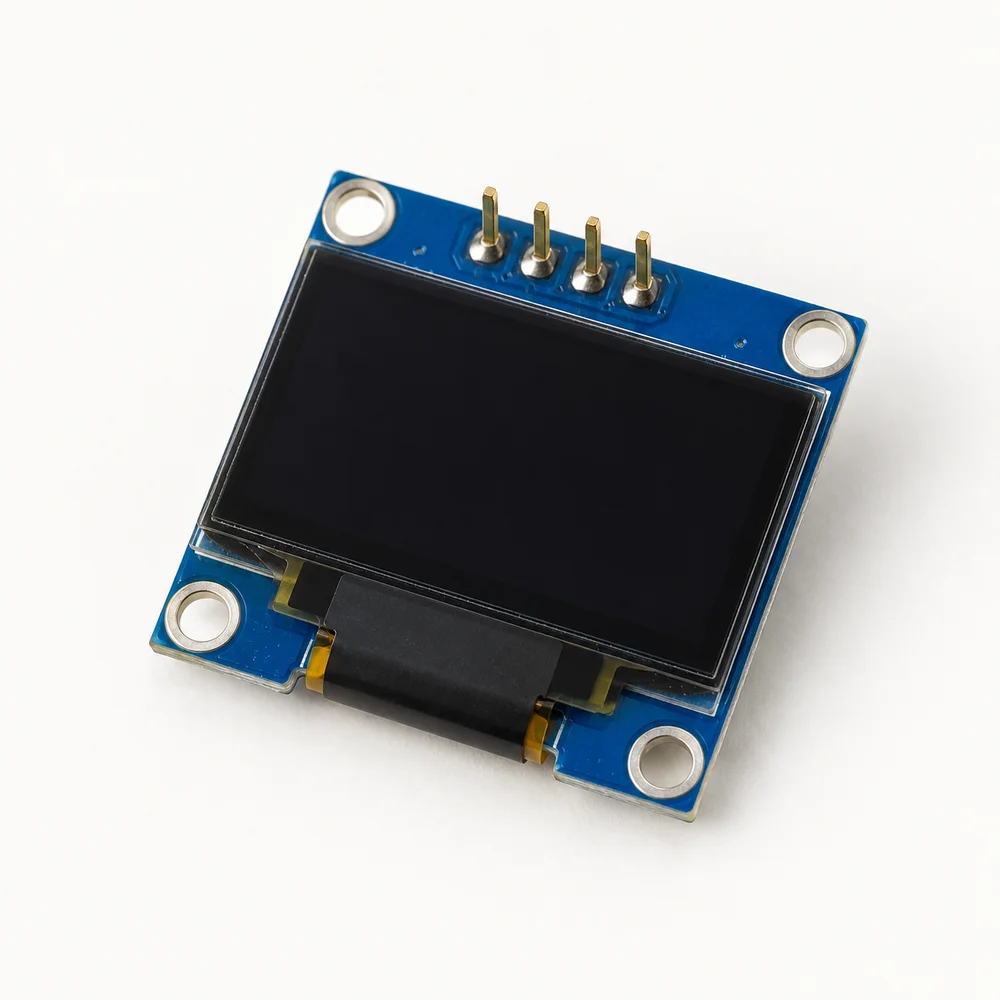
02Small OLED display on a blue circuit board with a row of connector pins.
In the kit: 1 pcs

0.96-inch OLED display

A compact screen for text, symbols and readings when a prototype needs its own display.

Explore component
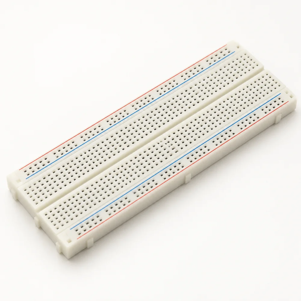
03White solderless breadboard with rows of holes, a central gap and side power rails.
In the kit: 1 pcs

830 tie-point breadboard

A solderless board for quickly assembling, checking and changing prototype connections.

Explore component
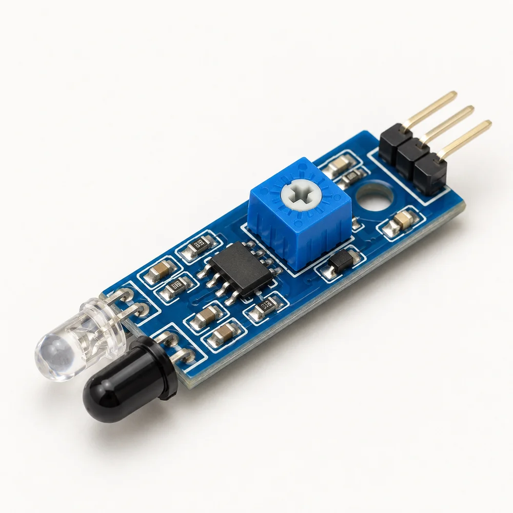
04Blue obstacle detection module with infrared emitter, receiver and adjustment trimmer.
In the kit: 1 pcs

Obstacle detection module

An infrared sensor for detecting objects in front of a module and triggering simple prototype responses.

Explore component
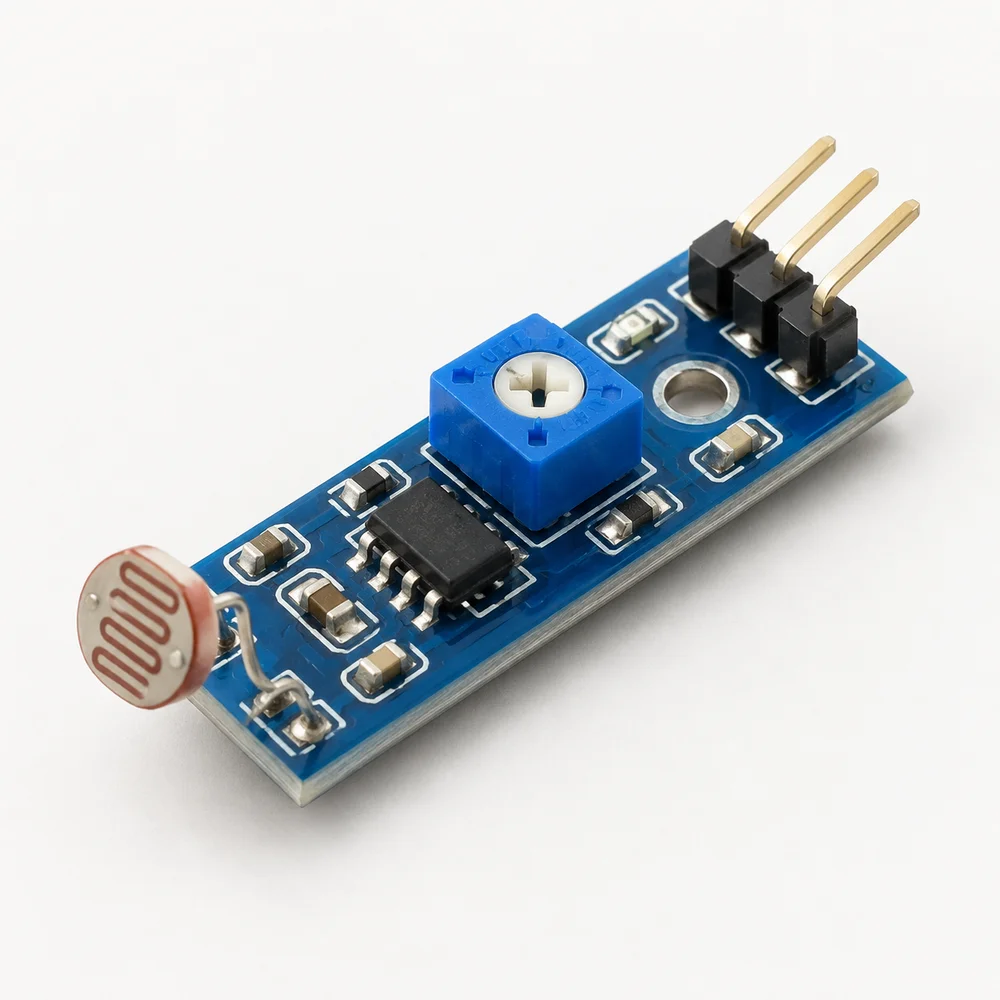
05Blue light sensor board with a round photoresistor and threshold adjustment trimmer.
In the kit: 1 pcs

Photoresistor light sensor module

Detects changes in illumination so a prototype can respond to light and darkness.

Explore component
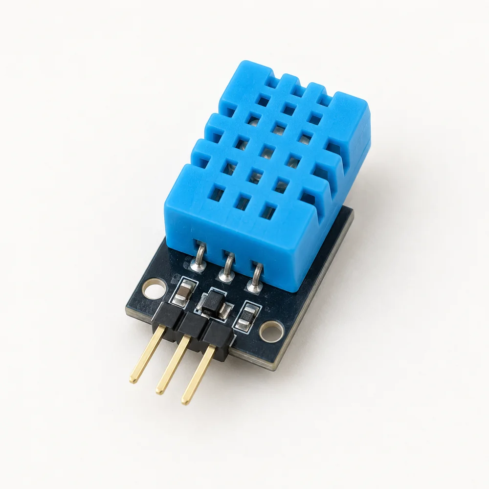
06Blue DHT11 sensor with a perforated enclosure on a small connector board.
In the kit: 1 pcs

DHT11 temperature and humidity module

A digital sensor module for first projects monitoring air temperature and relative humidity.

Explore component
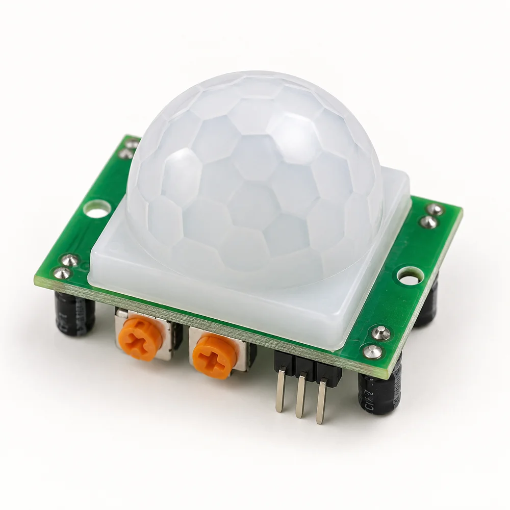
07PIR motion sensor with a white domed Fresnel lens on a green circuit board.
In the kit: 1 pcs

HC-SR501 PIR motion sensor

A passive infrared sensor responding to changes in thermal radiation within its field of view.

Explore component
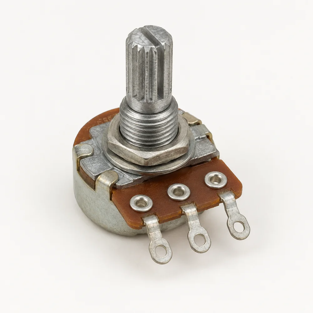
08Rotary potentiometer with a metal body, shaft and three electrical terminals.
In the kit: 1 pcs

10 kΩ potentiometer

An adjustable resistor with a shaft for setting values manually and learning about analogue inputs.

Explore component
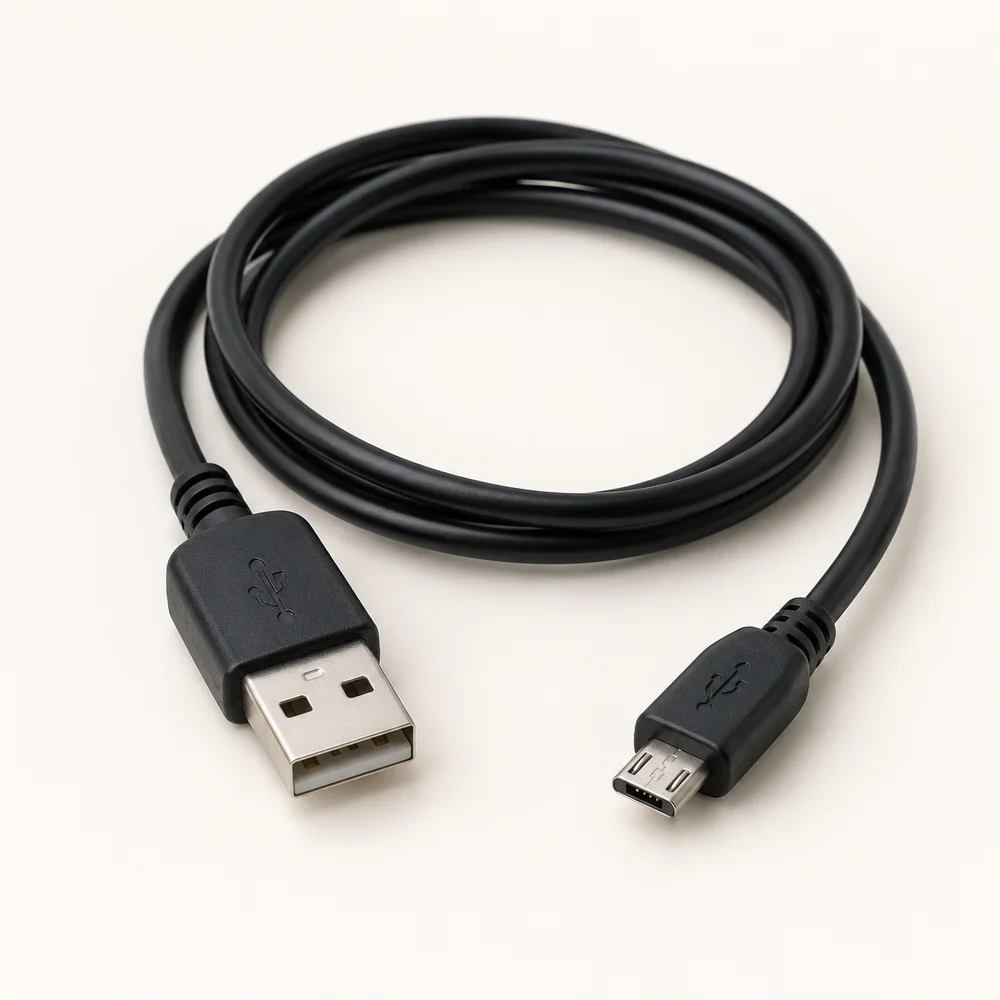
09Black USB cable with a standard USB-A plug and a smaller Micro-B plug.
In the kit: 1 pcs

Micro-USB cable

The connection between a computer and development board for power, programming and serial communication.

Explore component
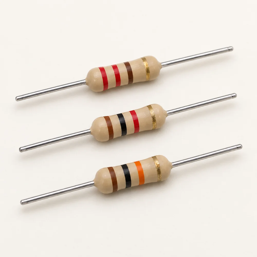
10Three axial resistors with coloured bands and metal wire leads.
In the kit: 30 pcs

Resistors — 220 Ω, 1 kΩ and 10 kΩ

Passive parts for limiting current, defining input states and building voltage dividers.

Explore component
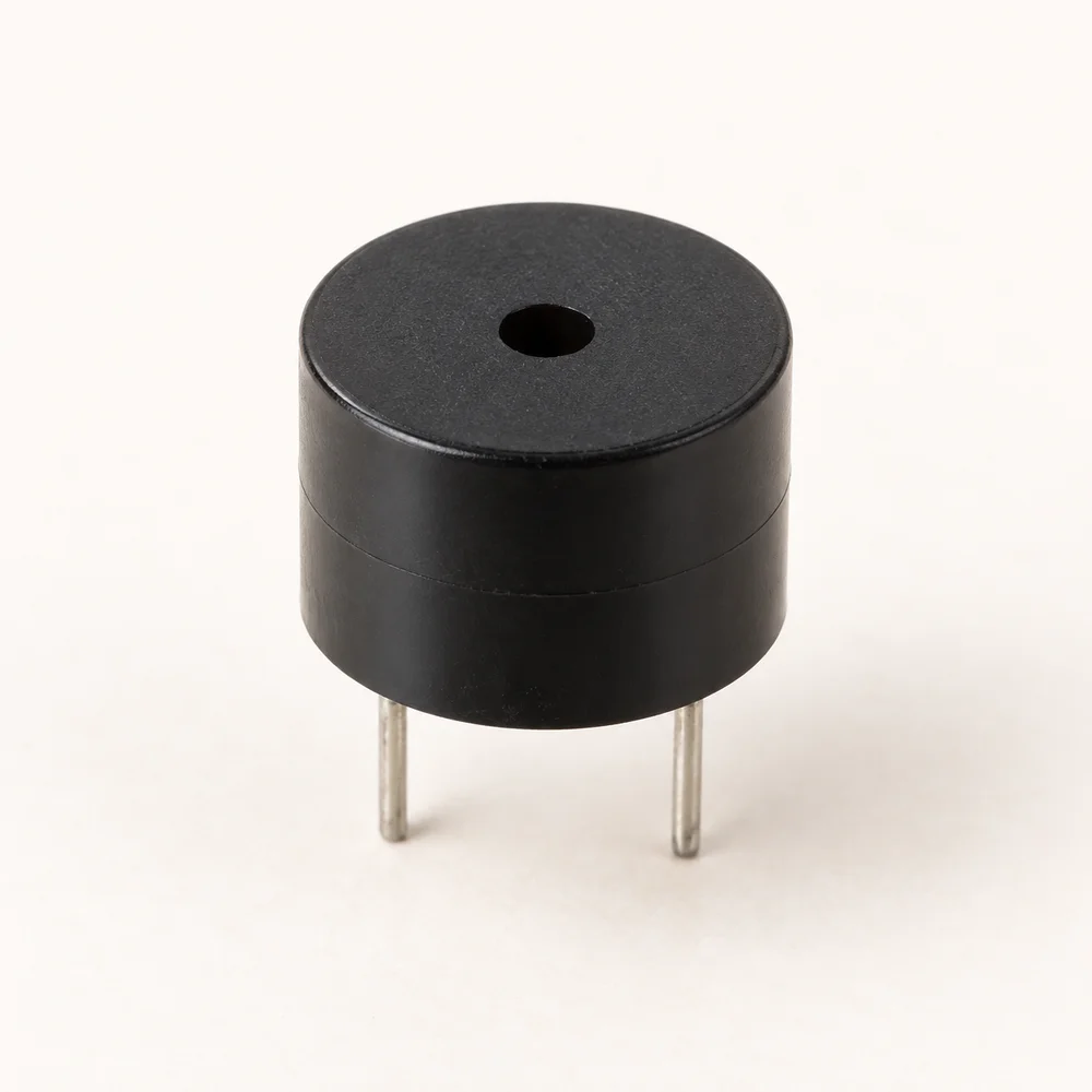
11Black cylindrical passive buzzer with a sound opening and two metal leads.
In the kit: 1 pcs

Passive buzzer

A sound component for tones and short melodies whose pitch follows an external drive signal.

Explore component
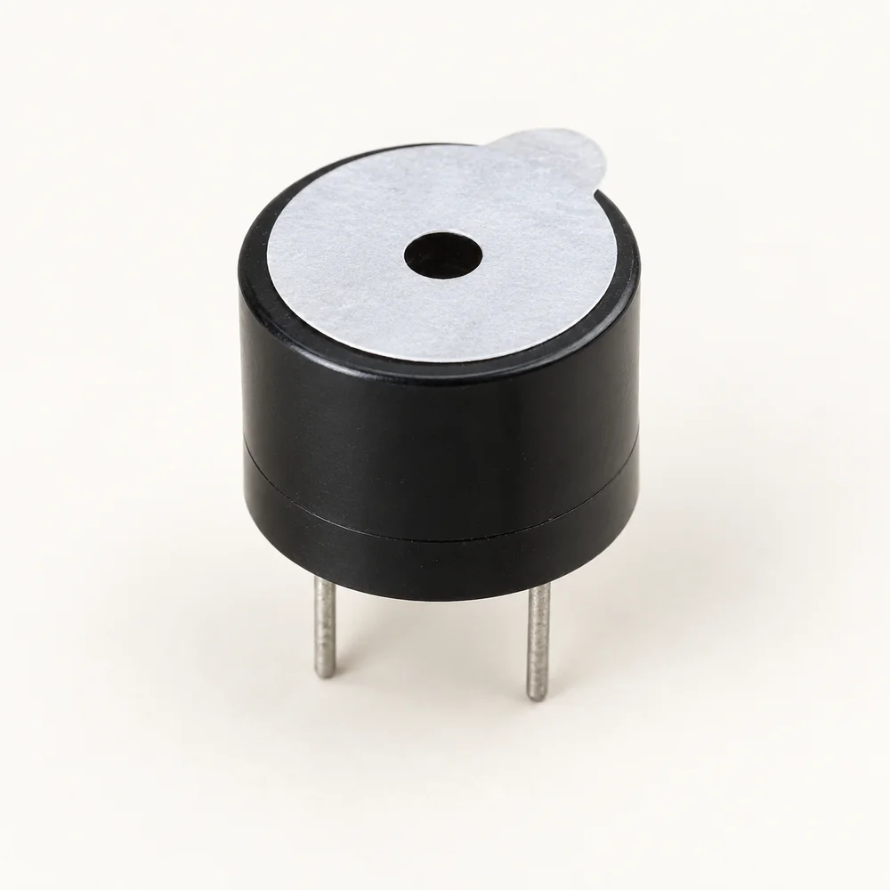
12Black active buzzer with a pale top sticker and two metal leads.
In the kit: 1 pcs

Active buzzer

A sound indicator with a built-in oscillator for simple signals, reminders and alerts.

Explore component
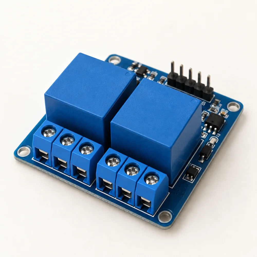
13Blue relay board with two relays and two groups of screw terminals.
In the kit: 1 pcs

5 V two-channel relay module

Two electromechanical switches for independently controlling low-voltage demonstration circuits.

Explore component
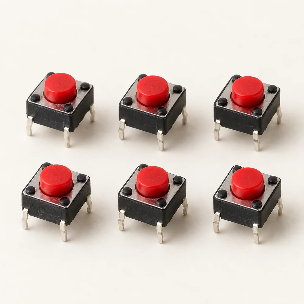
14Six pushbuttons with red caps, dark square bodies and metal contacts.
In the kit: 6 pcs

Pushbuttons

Six momentary switches for user input, press counting and prototype controls.

Explore component
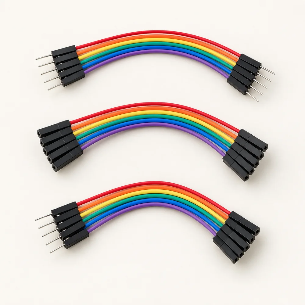
15Three colourful jumper-wire groups with male, female and mixed connectors.
In the kit: 30 pcs

Jumper wires — F–M, F–F and M–M

Three DuPont connector combinations for solderless links between boards, sensors and breadboards.

Explore component
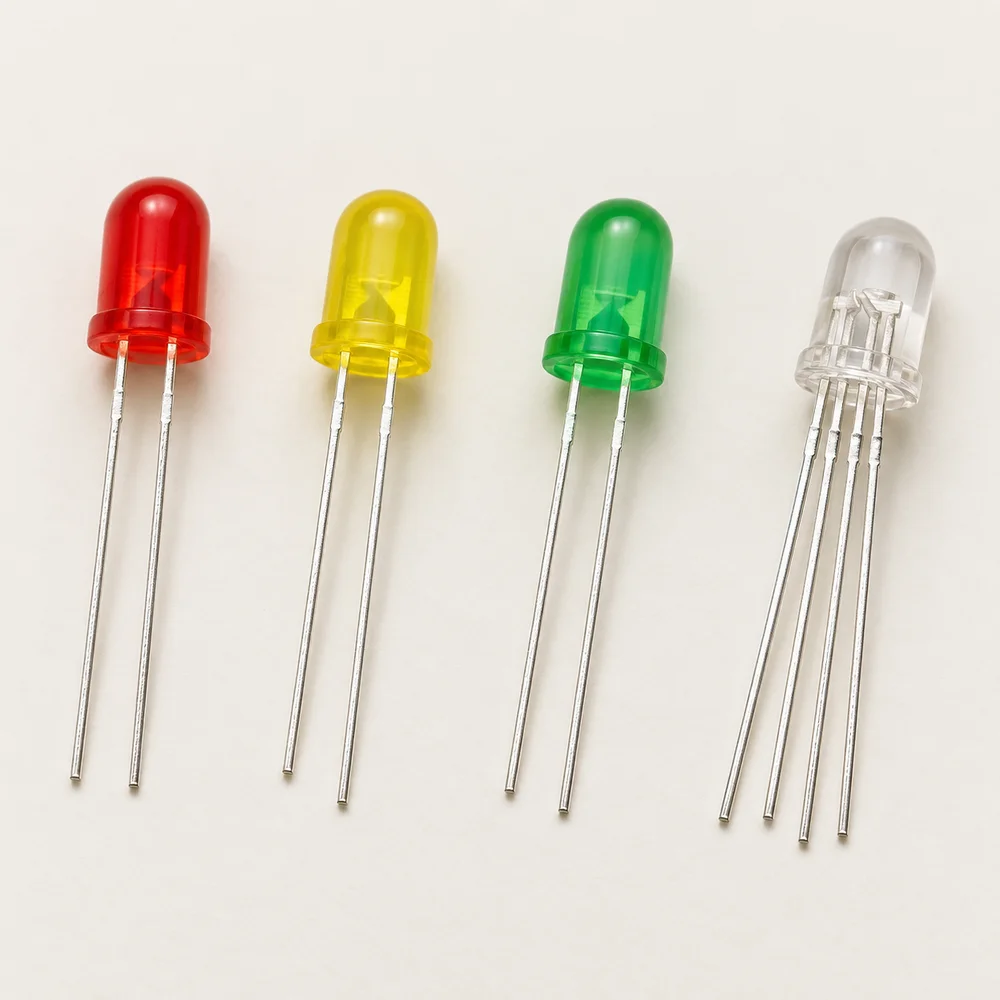
16Red, yellow and green two-lead LEDs beside a clear four-lead RGB LED.
In the kit: 17 pcs

LEDs — red, yellow, green and RGB

All kit LEDs in one article: light indicators, a traffic-light model and RGB colour mixing.

Explore component
Our ESP32 kit

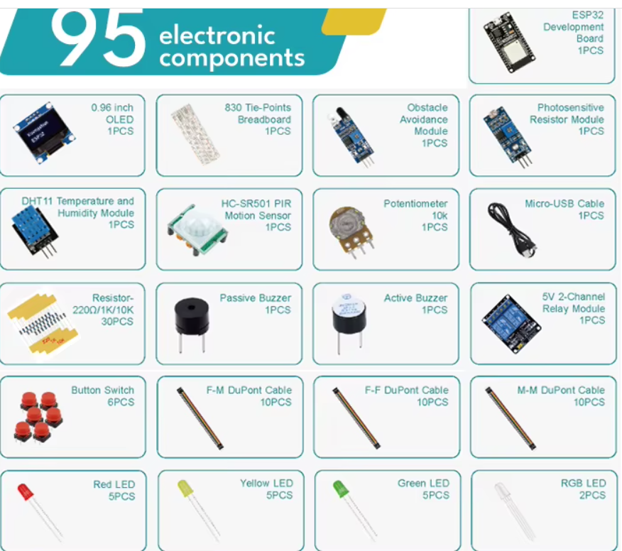
We purchased a simple ESP32 kit for introductory electronics and programming exercises. We will start with the components we already have, without complicated additions. According to the supplied image, the kit contains 95 pieces across 21 items.

What is included

ComponentQuantityPlanned use
ESP32 development board1Running programs and connecting components in exercises.
0.96-inch OLED display1Showing short messages and measured values.
830 tie-point breadboard1Assembling and changing simple connections.
Obstacle avoidance module1Exercises detecting an obstacle in front of the sensor.
Photosensitive resistor module1Observing changes in light levels.
DHT11 temperature and humidity module1Taking first temperature and humidity readings.
HC-SR501 PIR motion sensor1Motion detection exercises.
10 kΩ potentiometer1Changing a value by turning the shaft.
Micro-USB cable1Connecting the board; data transfer will be checked before the first exercise.
Resistors: 220 Ω, 1 kΩ and 10 kΩ30 in totalBasic circuits and LED exercises.
Passive buzzer1Introducing sound signals.
Active buzzer1Simple audible notifications.
Two-channel relay module, labelled 5 V1Introducing relay control in later exercises.
Push buttons6Giving commands by pressing a button.
Female–male DuPont wires10Linking matching component connectors.
Female–female DuPont wires10Linking matching component connectors.
Male–male DuPont wires10Linking matching component connectors.
Red LEDs5Visual indicators and first switching exercises.
Yellow LEDs5Visual indicators in exercises.
Green LEDs5Visual indicators in exercises.
RGB LEDs2Introducing different light colours.

Total: 95 pieces. The number 830 refers to the connection points on one breadboard. There are 30 resistors in total; the image does not specify the quantity of each resistance value.

Planned first exercises

We will progress gradually: a first LED, a button controlling an LED, reading a potentiometer, reading the DHT11 sensor and showing values on the OLED display. This is a plan for simple exercises, not a completed or verified course.

This inventory was transcribed from the supplied image of the purchased kit. The exact ESP32 board and OLED display models have not been established; their markings and connectors will be checked before wiring instructions are prepared.

Version: 1.0 · EN / SR

Open source image
